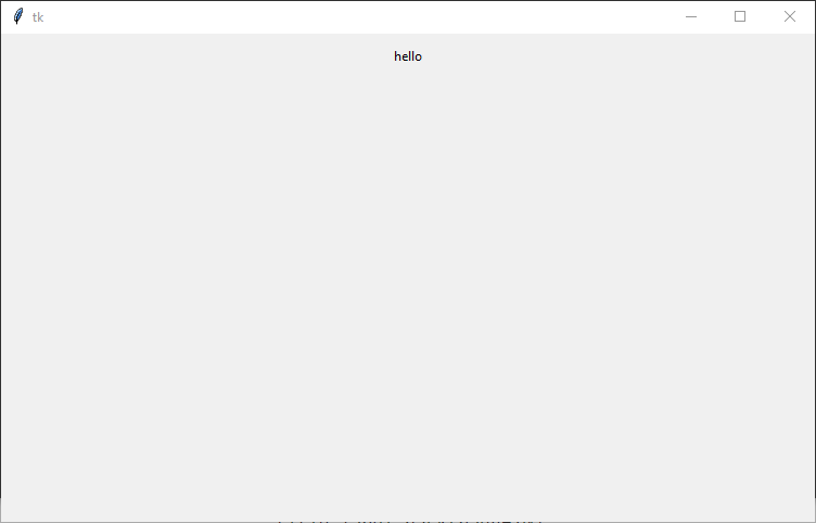
Below is the window with the label’s default font and style.
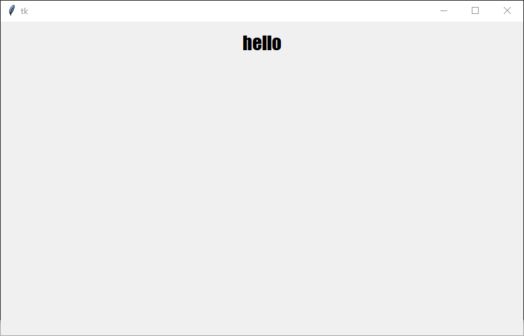
Next, we will add the font attribute to the label widget to customize the font style and size. In this example, we are going to change the font style to “Impact” and the font size to 20. The possible font styles are listed on the page https://learn.microsoft.com/en-us/typography/font-list/.
The aim of the tutorial is to display an image using Tkinter. The image will change when a button is pressed.
Step 1
Create the Tkinter window.
import tkinter as tk

win = tk.Tk()
win.geometry("750x450")

win.mainloop()
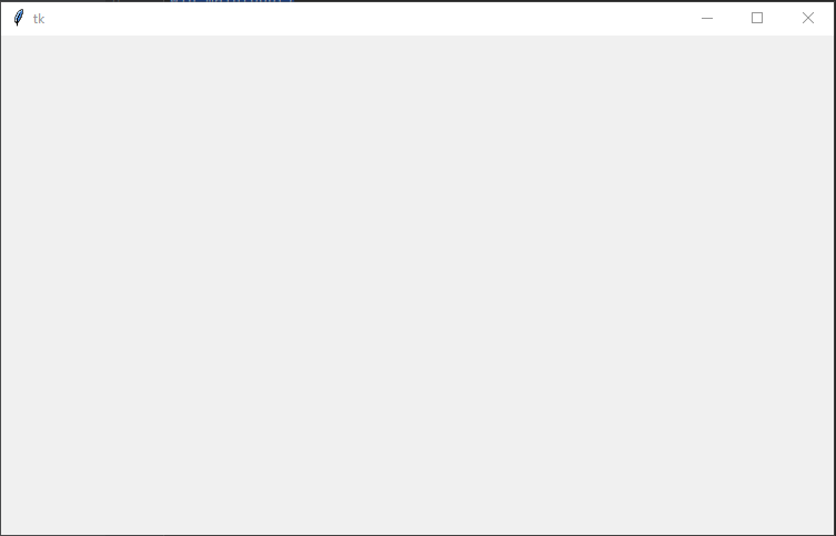
When executed the code should generate a window 750 by 450.
TK window
Step 2
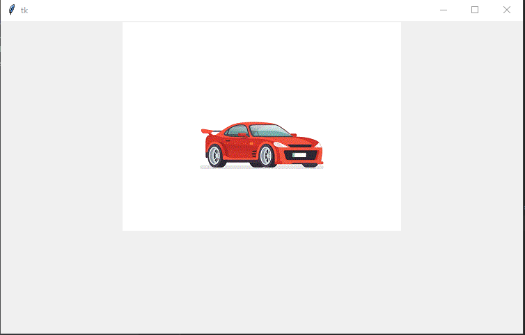
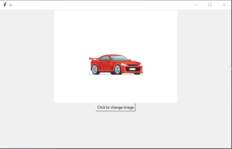
Display the image in the window. The code will load the image into a variable called photo. The code then adds a Label to the window of the type image and populates the label with the photo. In this example, the image is called car-jump.gif and the python code will assume the image file is in the same directory as the python code.
When executed the code will create a window with an image.
Step 4
Add a button to the window. First, we are going to add a button to the window and confirm the button will print a message when clicked. In the next step, we will link the button to the image.
import tkinter as tk


def change_image():
    print("Button has been clicked")


win = tk.Tk()
win.geometry("750x450")

photo = tk.PhotoImage(file='car-jump.gif')
image = tk.Label(win, image=photo)
image.pack()

button = tk.Button(win, text="Click to change image", command=change_image)
button.pack()

win.mainloop()
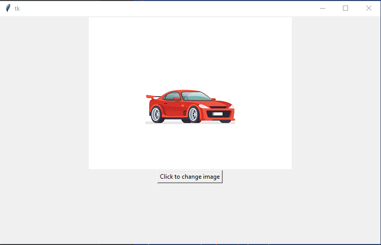
When executed the window should show the image and a button.
Tk window with image and button
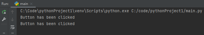
In the console window, you should see the message “Button has been clicked”, every time the button has been clicked.
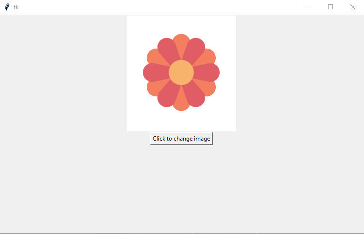
Step 5
In this step we will add the code to the change_image function that will change the image from car to a flower. In this example, the code assumes the flower.gif file will be in the same folder as the python code.
Symptoms
CNC machine Z Axis drops after completing job.
Relevant
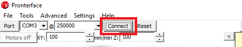
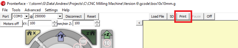
Marlin 3D Printer Firmware running on Arduino Mega with RAMPS 1.4 shield. Controlled via Pronterface.
Procedure
The steppers motors will shut down DEFAULT_STEPPER_DEACTIVE_TIME seconds after the last move when DISABLE_INACTIVE_? is true. Individual axis can be disabled or DEFAULT_STEPPER_DEACTIVE_TIME can be set to zero to stop the axis from dropping.
Open the firmware project
Open file Configuration_adv.h
Change the line from#define DEFAULT_STEPPER_DEACTIVE_TIME 120to#define DEFAULT_STEPPER_DEACTIVE_TIME 0
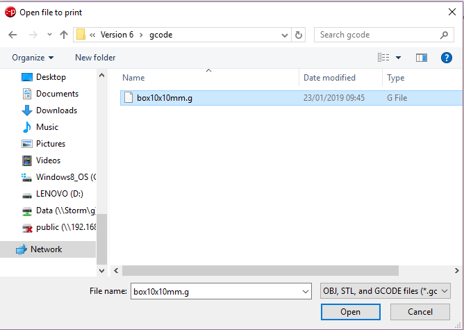
Symptoms
CNC machine homes in the wrong direction.
Relevant
Marlin 3D Printer Firmware running on Arduino Mega with RAMPS 1.4 shield.
Procedure
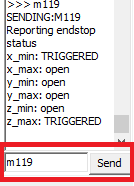
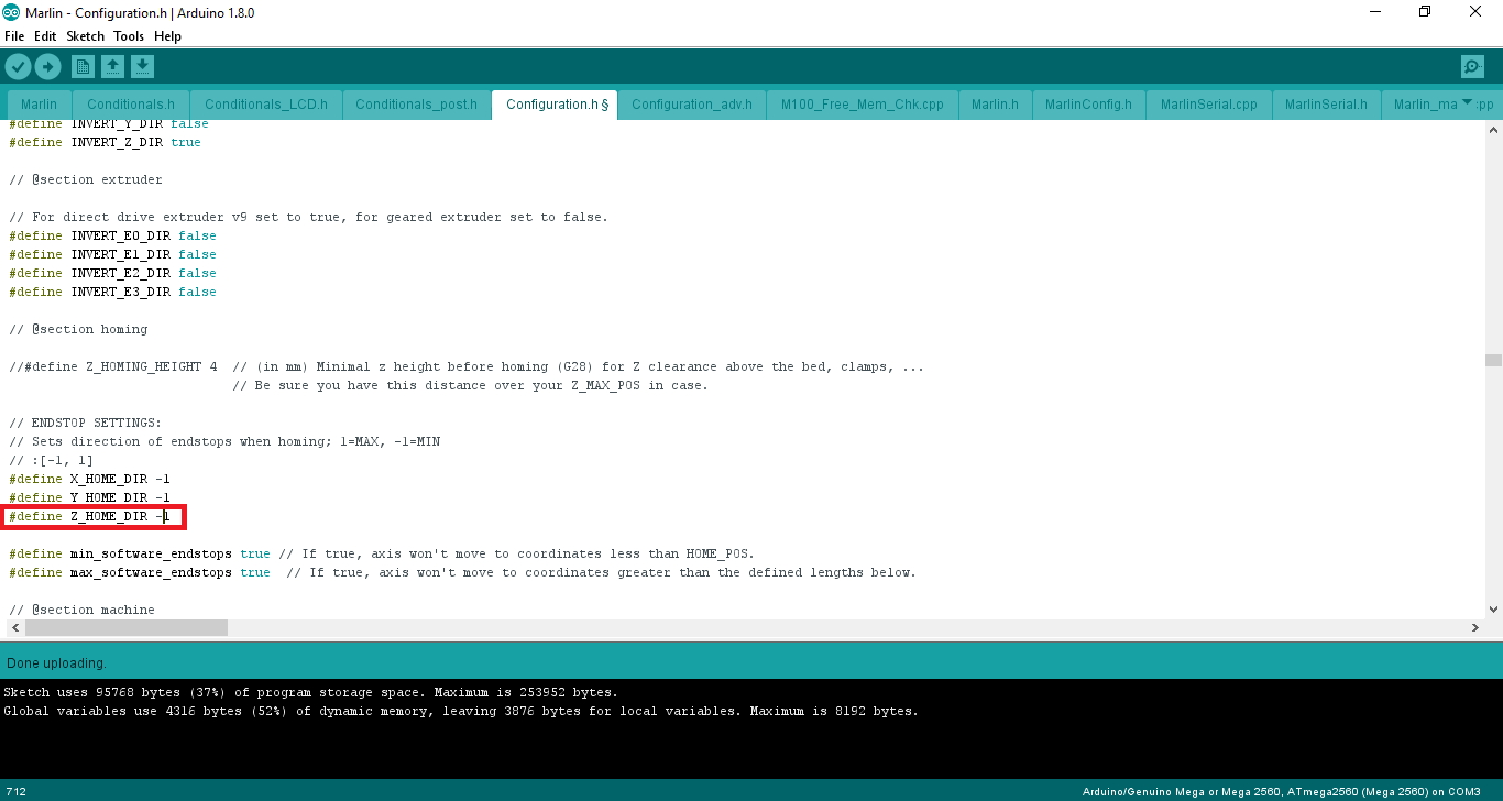
The direction of travel when homing is configured in the configuration.h using the settings X_HOME_DIR, Y_HOME_DIR and Z_HOME_DIR in the section ENDSTOP SETTINGS.
A value of -1 will set the homing direction towards the min end stop. A value of 1 will set the homing direction to the max end stop.
In the example below the homing direction for the z axis will be changed to home towards the max end stop.
The Z home value was -1 and has been changed to 1.
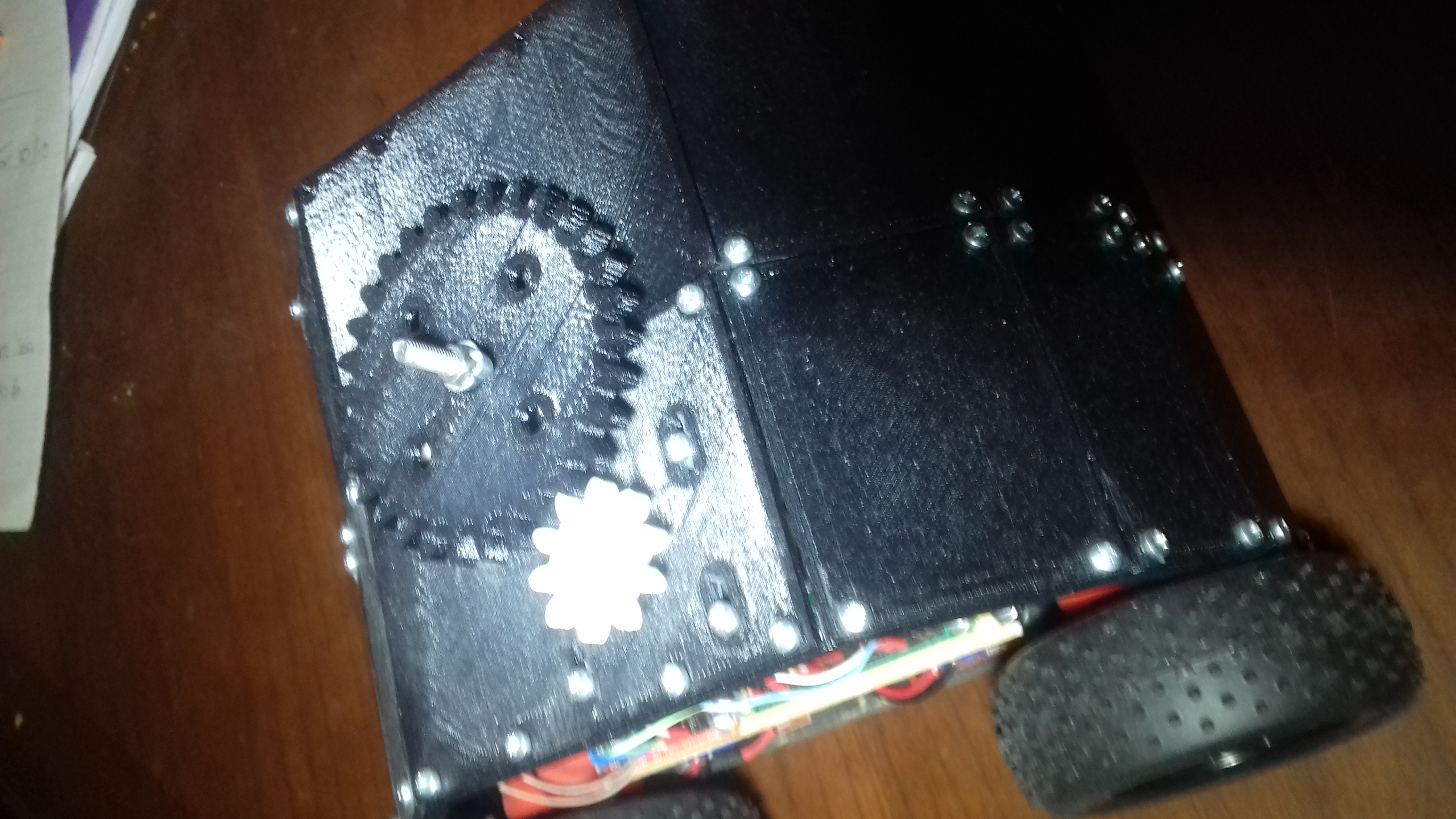
Today I have been busy developing a stepper motor service class. The service class will allow the Team Seaford robot to play crazy golf.
import RPi.GPIO as GPIO
import time

class ServiceStepMotor:

  PinPhase1 = 14
  PinPhase2 = 15
  PinPhase3 = 17
  PinPhase4 = 16

  Steps = [
  [1,0,0,0],
  [1,1,0,0],
  [0,1,0,0],
  [0,1,1,0],
  [0,0,1,0],
  [0,0,1,1],
  [0,0,0,1],
  [1,0,0,1]
  ]

  StepIndex = 0

  MotorOnTime = 0.05

  ## Constructor
  # @param self Class pointer
  def __init__(self):
    GPIO.setmode(GPIO.BCM)
    GPIO.setwarnings(False)

    self.SetPinToOutput(self.PinPhase1)
    self.SetPinToOutput(self.PinPhase2)
    self.SetPinToOutput(self.PinPhase3)
    self.SetPinToOutput(self.PinPhase4)
    pass

  ## Change pin type to output
  # @param self Class pointer
  # @param pin Pin Number
  def SetPinToOutput(self, pin):
    GPIO.setup(pin,GPIO.OUT)
    self.Off(pin)
    pass

  ## Turn output pin On
  # @param self Class pointer
  # @param pin Pin Number
  def On(self, pin):
    print "On="+str(pin)
    GPIO.output(pin,1)
    pass

  ## Turn output pin off
  # @param self Class pointer
  # @param pin Pin Number
  def Off(self, pin):
    GPIO.output(pin, 0)
    pass

  ## Change the output state of a pin
  # @param self Class pointer
  # @param PinNumber GPIO pin number
  # @param PinValue The new value for the GPIO pin
  def ChangeOuput(self, PinNumber, PinValue):
    GPIO.output(PinNumber, PinValue)
    pass

  ## Move stepper motor
  # @param self Class Pointer
  # @param Direction 1 = Forwards, 0 = Backwards
  def Step(self, direction):

    # Increment / decrement step count based on direction
    if (direction):
      # forward
      self.StepIndex += 1
    else:
      # backwards
      self.StepIndex -= 1

    # Check if we have passed the end of the steps list
    if (self.StepIndex >= len(self.Steps)):
      self.StepIndex = 0

    # Check if we have reached the start of the steps list
    if (self.StepIndex < 0):
      self.StepIndex = len(self.Steps) - 1

    # Set output pin states
    print "StepIndex=" + str(self.StepIndex)
    phase = self.Steps[self.StepIndex]
    self.ChangeOuput(self.PinPhase1, phase[0])
    self.ChangeOuput(self.PinPhase2, phase[1])
    self.ChangeOuput(self.PinPhase3, phase[2])
    self.ChangeOuput(self.PinPhase4, phase[3])
    #for i in range(len(phase)):
    #  self.On(phase[i])

    # Delay while motor turns
    time.sleep(self.MotorOnTime)
    pass
The example code below shows how to use the stepper motor service class.
import ServiceStepMotor
sm = ServiceStepMotor.ServiceStepMotor()

print"Start"

print "Step forwards 10 steps"
for i in range(10):
  print "Step forward " + str(i)
  sm.Step(True)

print "Step backwards 10 steps"
for i in range(10):
  print "Step backward " + str(i)
  sm.Step(False)

print "Finish"
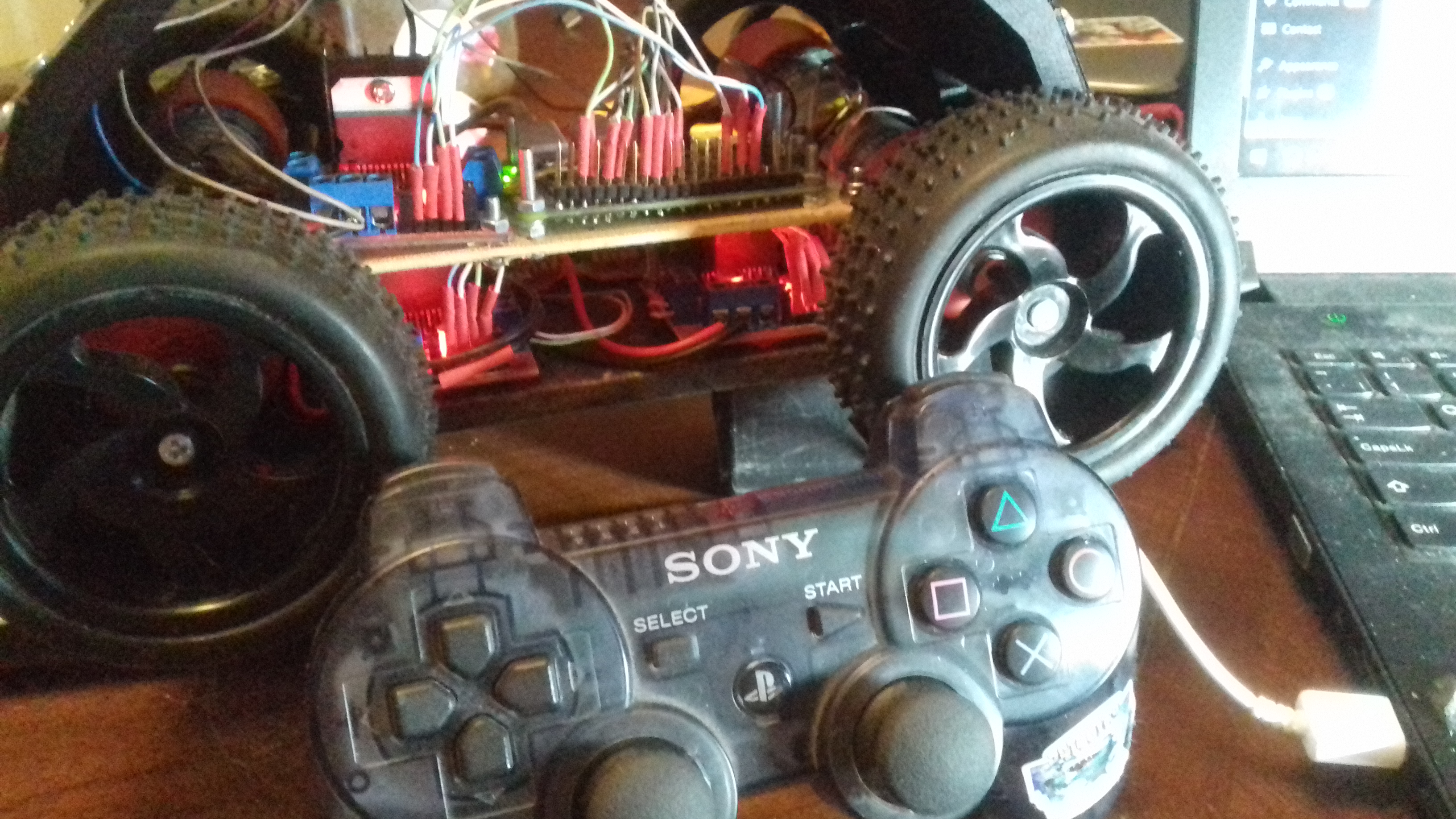
We used WIFI to control our 2015 Pi Wars robot. Using WIFI was a big mistake. On the day of the competition, there was too much interference and lag. We have learnt from our mistakes. This time we will be using Bluetooth.
We have connected a USB Bluetooth dongle to the Raspberry Pi and using the instructions below connected a Sony Playstation Six Axis Controller.
Using micro usb cable plug in the PS3 controller into the raspberry pi
Enter the command sudo ./sixpair
Disconnect USB cable from PS3 controller
Enter the command bluetoothctl
Enter the command devices
Enter the command agenton
Enter the command trust followed by the MAC address of the controller. In my case the MAC address is 00:06:F5:C4:01:3b.trust 00:06:F5:C4:01:3b
Disconnect the usb cable
Press the PS button the top of the controller
Confirm the new input device has been succesffully added. Enter the command sudo ls /dev/input you should see JS0 has been added to the list of input devices
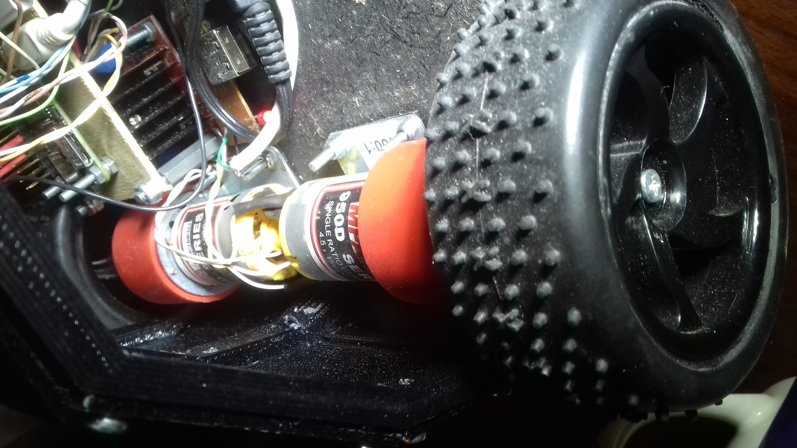
Our robot is alive and moving. At the heart of the Team Seaford robot control is the ServiceIo class. The ServiceIo class is responsible for controlling the four drive motors. Each motor is connected to a H bridge motor controller. The H bridge controllers require two inputs per motor. The inputs control the direction of travel.