Getting Started With FreeCAD: Spreadsheets and Parametric Design
Introduction
Parametric design allows you to define the dimensions of your model using parameters. These parameters can be stored in a spreadsheet, making it incredibly easy to update your design. Change a value in the spreadsheet, and your 3D model will automatically update to reflect the new dimension. This saves you time and effort, especially in complex projects.
This guide will walk you through the process of creating a simple parametric cube in FreeCAD. You will learn how to:
- Create a spreadsheet to store your design parameters.
- Link the dimensions of your 3D model to the values in the spreadsheet.
- Modify your model by simply changing the values in the spreadsheet.
By the end of this tutorial, you'll have a solid understanding of how to use spreadsheets to create parametric designs in FreeCAD.
Getting Started
Step 1: Create a Spreadsheet
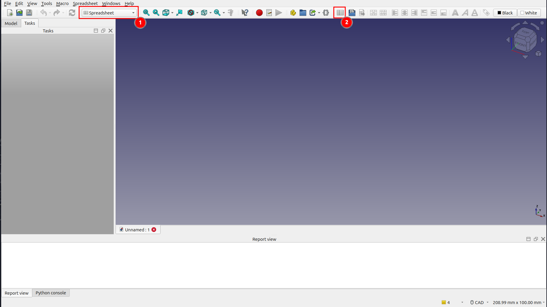
- From the toolbar dropdown, select the Spreadsheet workbench.
- Click on the Create Spreadsheet icon to create a new spreadsheet.
Step 2: Define Your Parameters
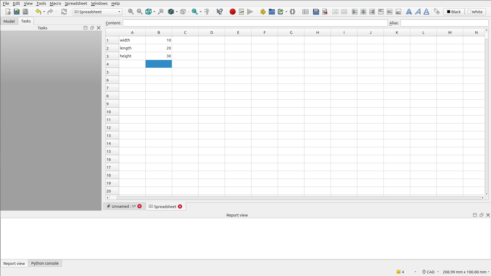
- Enter the following values into the spreadsheet:
| A | B | |
|---|---|---|
| 1 | Width | 10 |
| 2 | Length | 20 |
| 3 | Height | 30 |
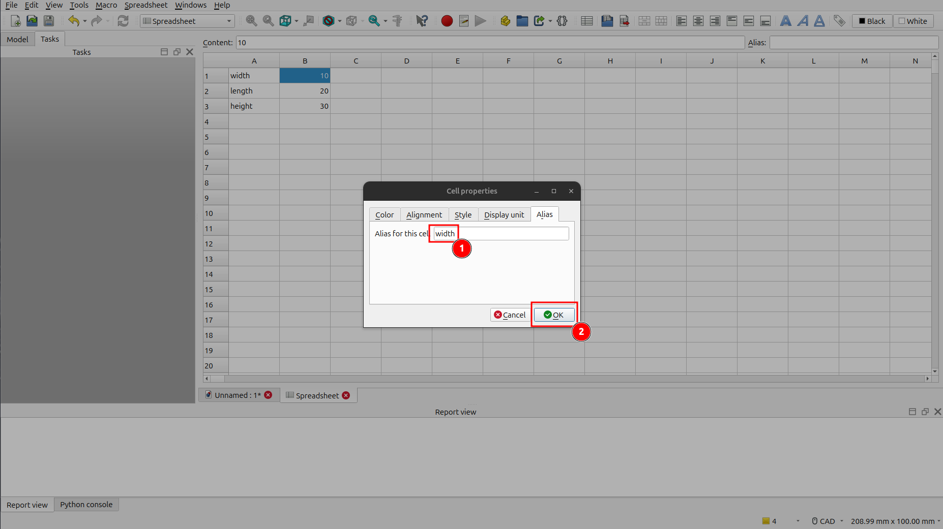
Step 3: Set Aliases for Your Parameters
To make our parameters easier to reference, we'll give them aliases.
- Right-click on cell B1 (which contains the value
10) and select Properties from the context menu. - In the Cell Properties window, go to the Alias tab.
- Enter
widthas the alias and click OK.
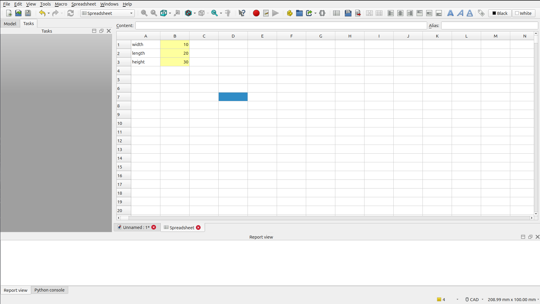
- Repeat this process for cells B2 and B3, using the aliases
lengthandheightrespectively.
Once you've set the aliases, the cells should be highlighted in yellow, indicating that they have an alias.
Step 4: Create the 3D Model
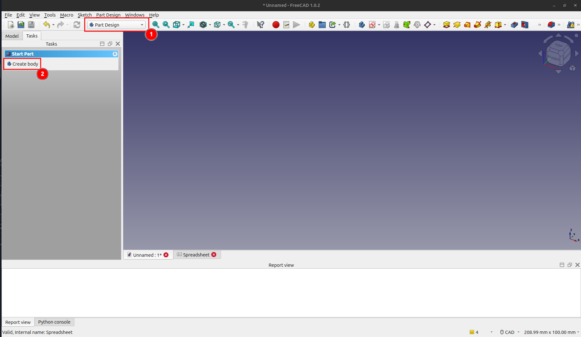
- From the toolbar dropdown, select the Part Design workbench.
- Click on the Create Body icon to create a new body for our model.
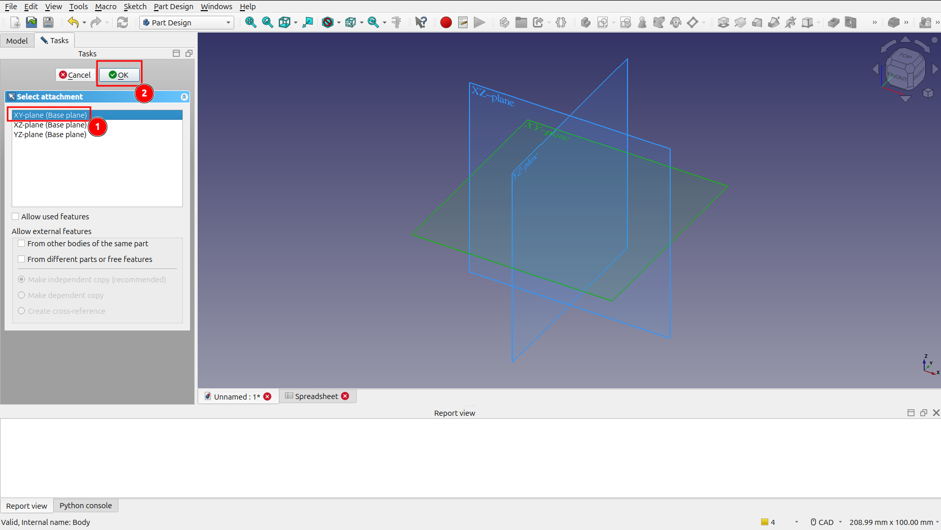
- Click on Create sketch to start sketching our model.
- Select the XY-plane (Base plane) and click OK.
Step 5: Draw the Base of the Cube
- Click on the Create Rectangle icon and draw a rectangle of any size in the sketch editor.
Step 6: Link the Sketch to the Spreadsheet
Now, we'll link the dimensions of the rectangle to the parameters in our spreadsheet.
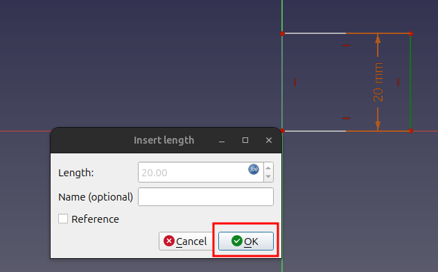
- Select the vertical constraint of the rectangle. Click on the f(x) icon next to the length value to open the Formula Editor.
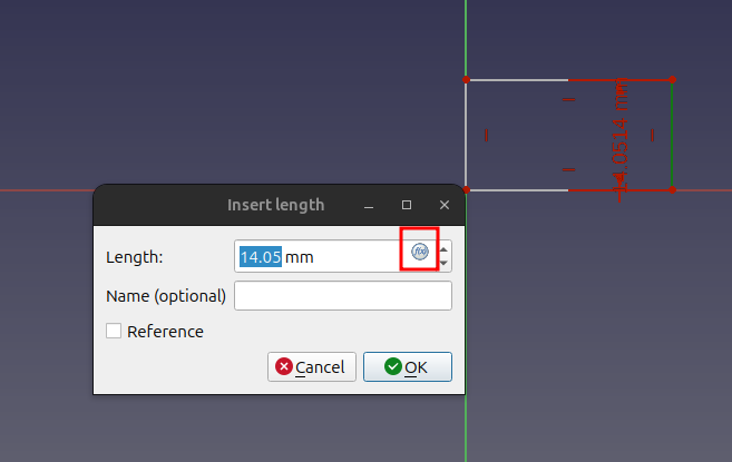
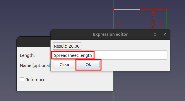
- In the Formula Editor, enter
Spreadsheet.lengthand click OK.
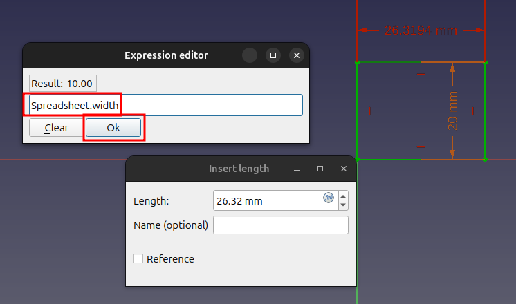
- Next, select the horizontal constraint of the rectangle. Click on the f(x) icon next to the height value to open the Formula Editor.
- In the Formula Editor, enter
Spreadsheet.widthand click OK.
- Click Close to close the sketch editor.
Step 7: Create the Pad
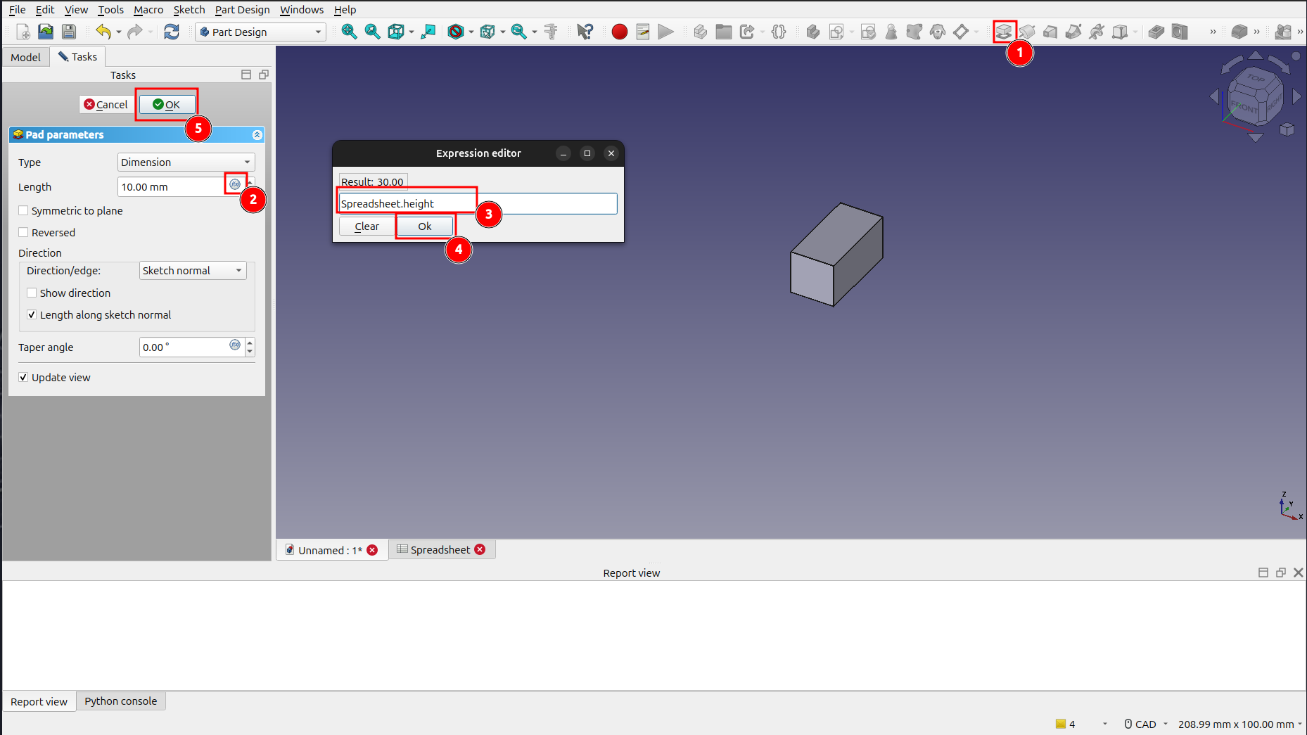
- With the sketch selected, click on the Pad icon to extrude the rectangle into a 3D shape.
- In the Pad parameters, click on the f(x) icon next to the Length value.
- In the Formula Editor, enter
Spreadsheet.heightand click OK. Then, click OK again to create the pad.
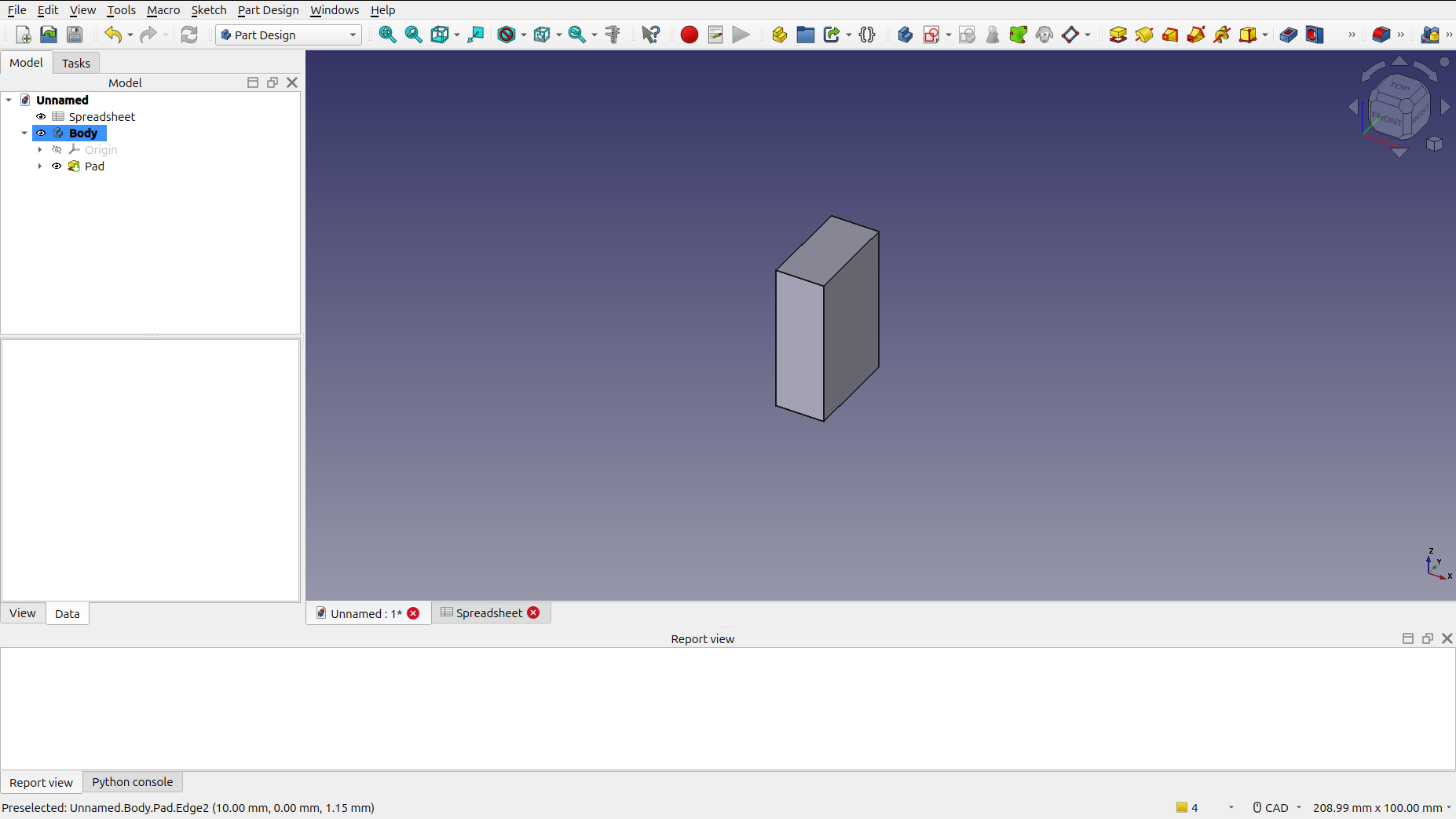
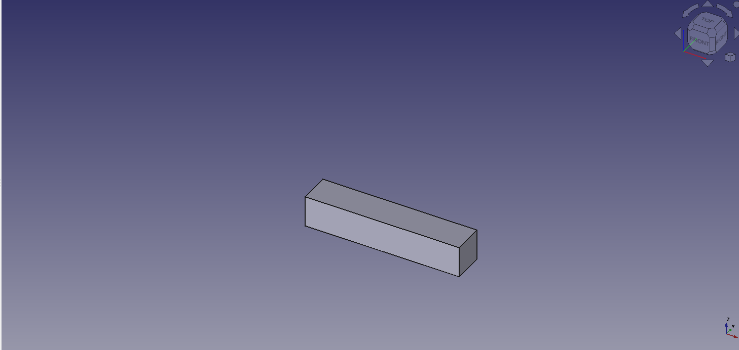
Step 8: You're Done!
Congratulations! You have successfully created a parametric cube.
Now for the fun part! Go back to the Spreadsheet tab and change the values for width, length, and height. You'll see the cube automatically resize itself based on your changes.

Conclusion
In this tutorial, you've learned the fundamentals of parametric design in FreeCAD. By using a spreadsheet to control the dimensions of your model, you can create flexible and easily modifiable designs. This is a powerful technique that can save you a lot of time and effort in your projects.
Now that you understand the basics, you can start exploring more complex parametric designs. Happy modeling!